micro Stress vs Strain Machine
Drawingboard Return
instron: redo, this is untenable and no one should build one https://www.amazon.com/SFU1605-Ballscrew-RM1605-Housing-Machine/dp/B07DQK2YFN/ misumi for drive components / checkin ... beams all the way down, overconstrained, and motors in front nut-in-hole type threading, 10mm width S5M pulley: but check torque spec
- at this width keyless works very well w/ 16mm total width https://us.misumi-ec.com/vona2/detail/110300409350/?CategorySpec=00000045557%3a%3ac
- compare: fancy-ass pulleys with medium reduction, or 1/2" -> 10mm coupling and NEMA34 ? ... consider that reasonable torques for a shaft coupling are '35 - 53' in-lbs (from McMaster search: 2764K424 or 2464K34) - that's about 5.6 Nm, a NEMA34 does ~ 5-8Nm at the upper end, so it's in threshold
- coupling is ~ $100 each for well-spec'd, $72 each for ok-spec'd ... pulleys are probably similar once you've done 2x pulleys and 1x belt, with fancy shit... and pulleys afford smaller motors that you can actually drive,
- if, however, you can find cheap couplings, to spec (probably not) you can do that. get your spreadsheets back out !
Generating kN
We want lots of force, with very fine control of position. This means a nice linear transmission. To estimate the forces we might want to see, I wrote a quick table of forces required to rip apart ~ 3mm square (0.001mm^2) samples of a few materials.
| Material | Yield (MPA) | F at Break (N) |
|---|---|---|
| ABS | 40 | 360 |
| Nylon 6 | 70 | 630 |
| HDPE | 15 | 135 |
| 6061 ALU | 310 | 2790 |
| 4140 Stainless | 655 | 5895 |
| 6AL-4V Ti | 950 | 8550 |
Brinell hardness tests range from 10N through to 30kN (for steel and cast iron) but non-ferrous materials normally see 5kN only.
So, a ballpark of ~ 10kN would be ideal - this is a big number - off the bat I'm going to estimate that 5kN will be a more reasonable target. 1kN is enough for a complete set of plastics, but that's only allowing for a realtively small sample.
To generate the force required, we're going to need some motor / transmission oomph. Here's a list of typical NEMA size motors, and the torques they can generate. The atkstepper can supply enough current to power any of these.
| Motor | kg | Nm |
|---|---|---|
| N23 56mm | 1.2 | 1.3 |
| N23 100mm | 1.8 | 3.0 |
| N34 68mm | 1.8 | 3.4 |
| N34 156mm | 5.4 | 13.0 |
| N42 150mm | 10.9 | 22.0 |
Racks and Pinions
We'll be using two linear stages (one on either side of the platform), so, from our N34 156mm motor with 13Nm of torque we'll need 26, 5.2 and 2.6mm lever arms respectively for 1, 5 and 10kN total force.
Considering practical limits on pinion diameter (with a shaft of 14mm, and 19 3mm-pitch teeth, we'll have an 18mm diameter pinion - 9mm lever arm) we will only realistically achieve 1.44kN of linear force per motor with direct-drive rack and pinion on a Nema 34 size motor. This makes a 3kN machine, but to add some safety factor we're at at 2kN goal with this approach.
The next step would be to check against tooth shear stress for 3mm pitch.
From reasonable WEDM (time) and Waterjet (washout) limits, I expect the thickness of any fabricated pinion to have a limit around 12mm. To make this all simple, I'll say 10mm. For the waterjet, this is a bit of a stretch (get it?)...
To guess at resolutions, we'll take our sample above in aluminium having a length of 100mm - with elongation at break being 12%, we're interested in a 12mm 'long' stress / strain curve. For 1000 pts on this curve, we're interested in a step size of 12 microns.
From our 18mm diameter pinion having a circumference of 56mm, this means 4667 counts per revolution. In a 200-step motor, we would need 32 microsteps per revolution - most drivers will go to 256 - but microstepping isn't exactly linear. To do this really well, we will want to finish work on closed loop stepper driving, where we can use a 14-bit encoder to control around ~ 4096 counts reliably.
All in, a direct rack and pinion drive can land us at a 2kN machine with some desired resolution, but we're at or near most of the limits here.
Belts
Since I was spinning this up to test on a belt-driven gantry system, I was able to confirm that this is a bad idea. We defeat the elastic stretch of the belt by measuring at the specimen (not through the machine's structural loop) but a meagre GT2 belt profile skips teeth pretty quickly as we approach any tens of kilos of load.
Ball or Leadscrews
Racks aside, a ballscrew is the obvious way to do this. Ballscrews can be had for less than hundereds of dollars. Besides transmitting motion smoothly, their ratios are favourable. For example, with a 5mm pitch ballscrew having an efficiency of 85%, we can drive 14kN with our 13Nm motor - so 28kN for the machine.
For the same ballscrew, to achieve 12 micron resolution we'll only need 416 steps in each rotation - this is easy to get.
Design Spec / Notes
The goal here is to design and build a machine, which can be fabricated in $250k size fab labs, that can generate stress-strain curves for a wide set of materials as well as perform hardness testing.
To ballpark, I'd like to see 100mm diameter plates having a total travel from 0mm separation -> 500mm, this leaves enough room for fixturing etc.
Sam's note: the ballscrews should be 'pulling' in all cases. Against their fixed, driven side. This is a good note, thank you sam.
Step Two: Force Measurement
For load measurement, Sam has worked through a great loadcell design.
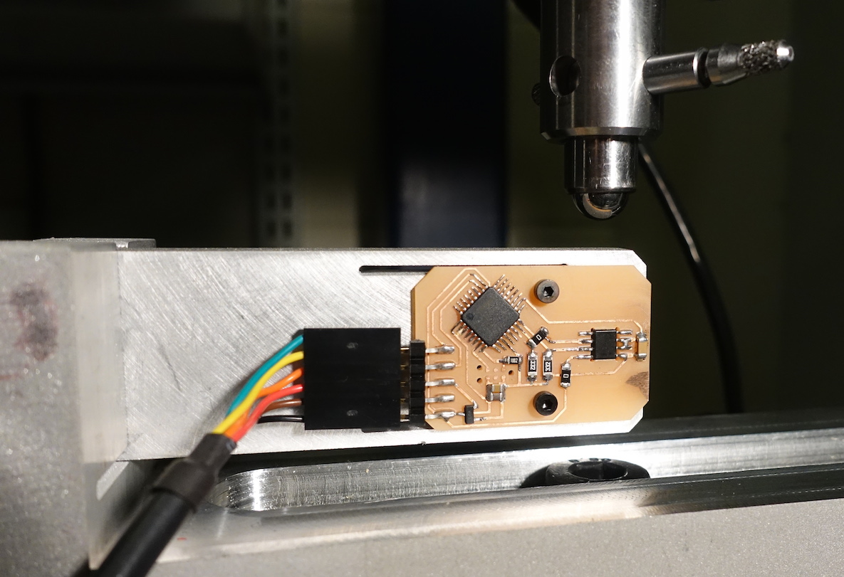
Ok, doing this with a wheatstone-bridge type load cell now.
I believe I want my ADC to have the green line 'on top' and white on the bottom, of a differential channel.
Fixturing
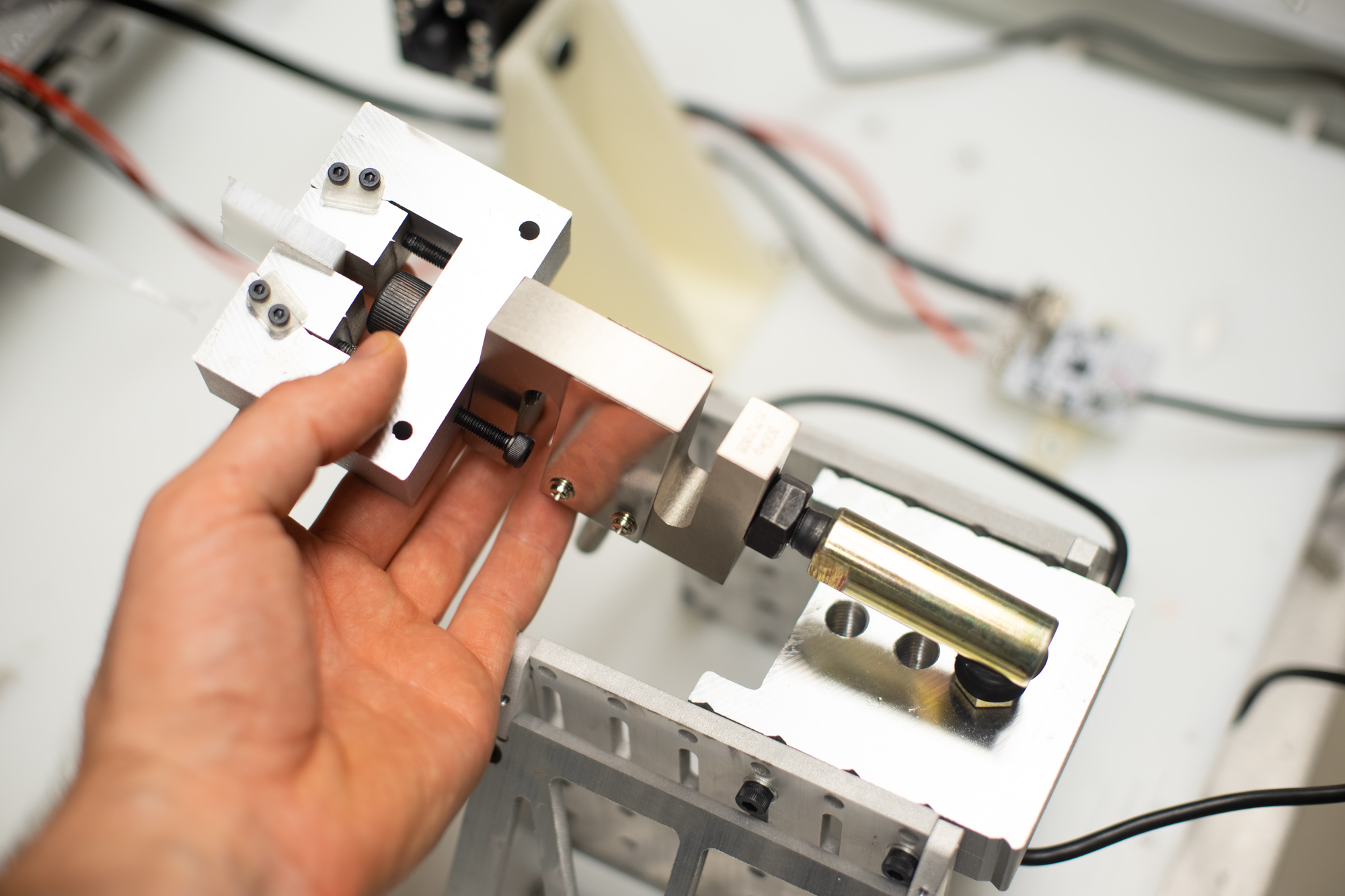
! important
uSSM #2
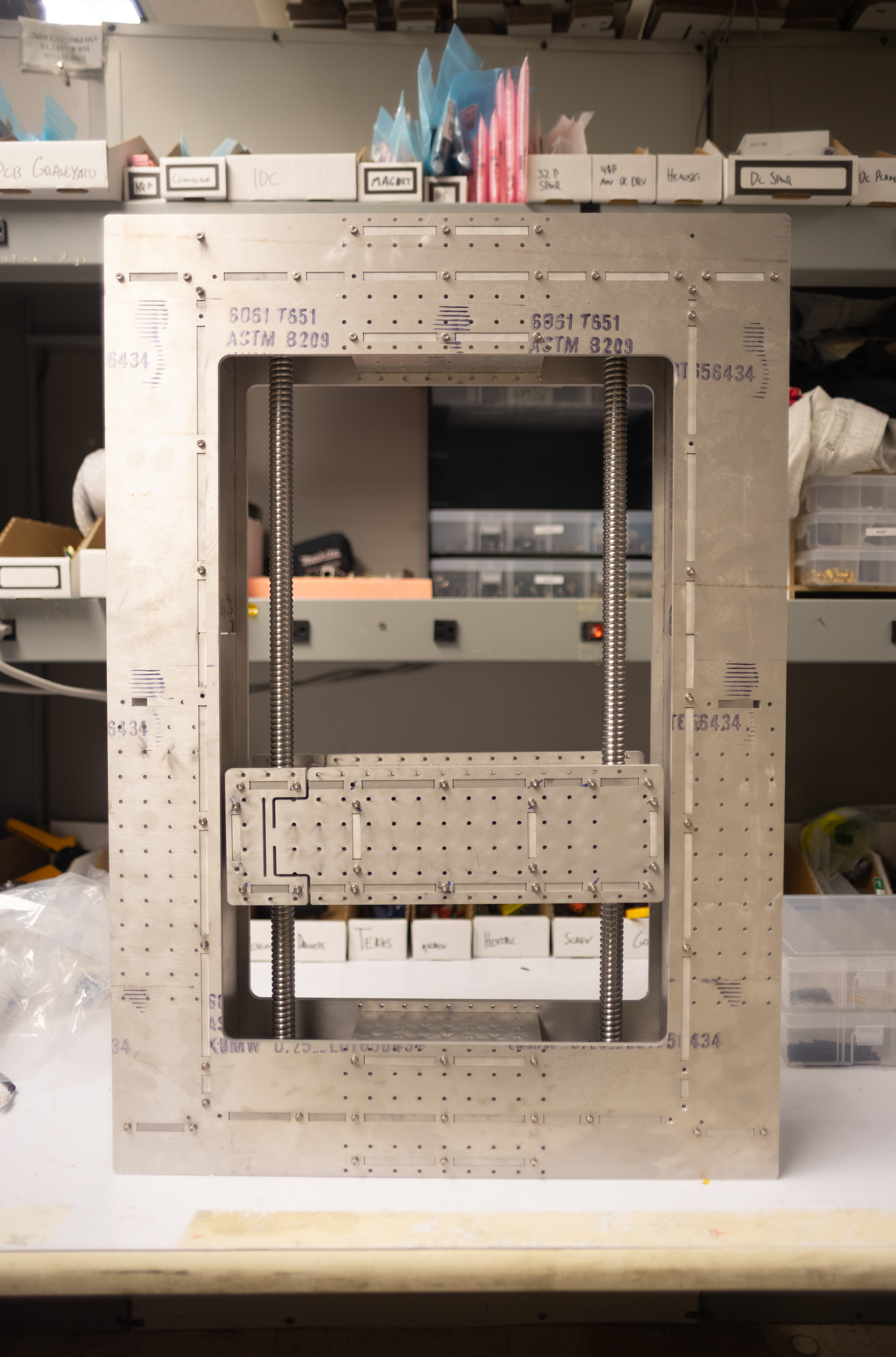
status machine is designed, fabricated, waiting for adaption of fixturing from 'the generalist' and for squid works controllers.
Dedicated uSSM
Here I'm using some
-
Ballscrews, SFU2005 C7 700mm Long ebay, $150
-
Nema 23 Motors w/ .25" Shaft
-
GT2 5mm 6.35mm Bore Pulley 12T for 15mm Belt 'A 6A55-012DF1508'
-
GT2 5mm 12mm Bore Pulley 48T for 15mm Belt 'A 6A55M048NF1512'
-
GT2 5mm 15mm Belt with 55T 'A 6R55M055150'
-
http://shop.sdp-si.com/catalog/product/?id=A_6R55M055150 55T 15mm Closed GT2 Belt
-
http://shop.sdp-si.com/catalog/product/?id=A_6A55-012DF1508 12T 0.25" bore Pulley 15mm
-
http://shop.sdp-si.com/catalog/product/?id=A_6A55M048NF1512 48T 12mm Bore
-
http://shop.sdp-si.com/catalog/product/?id=A_6A55M044NF1512 44T
-
http://shop.sdp-si.com/catalog/product/?id=A_6A55M050NF1512 50T
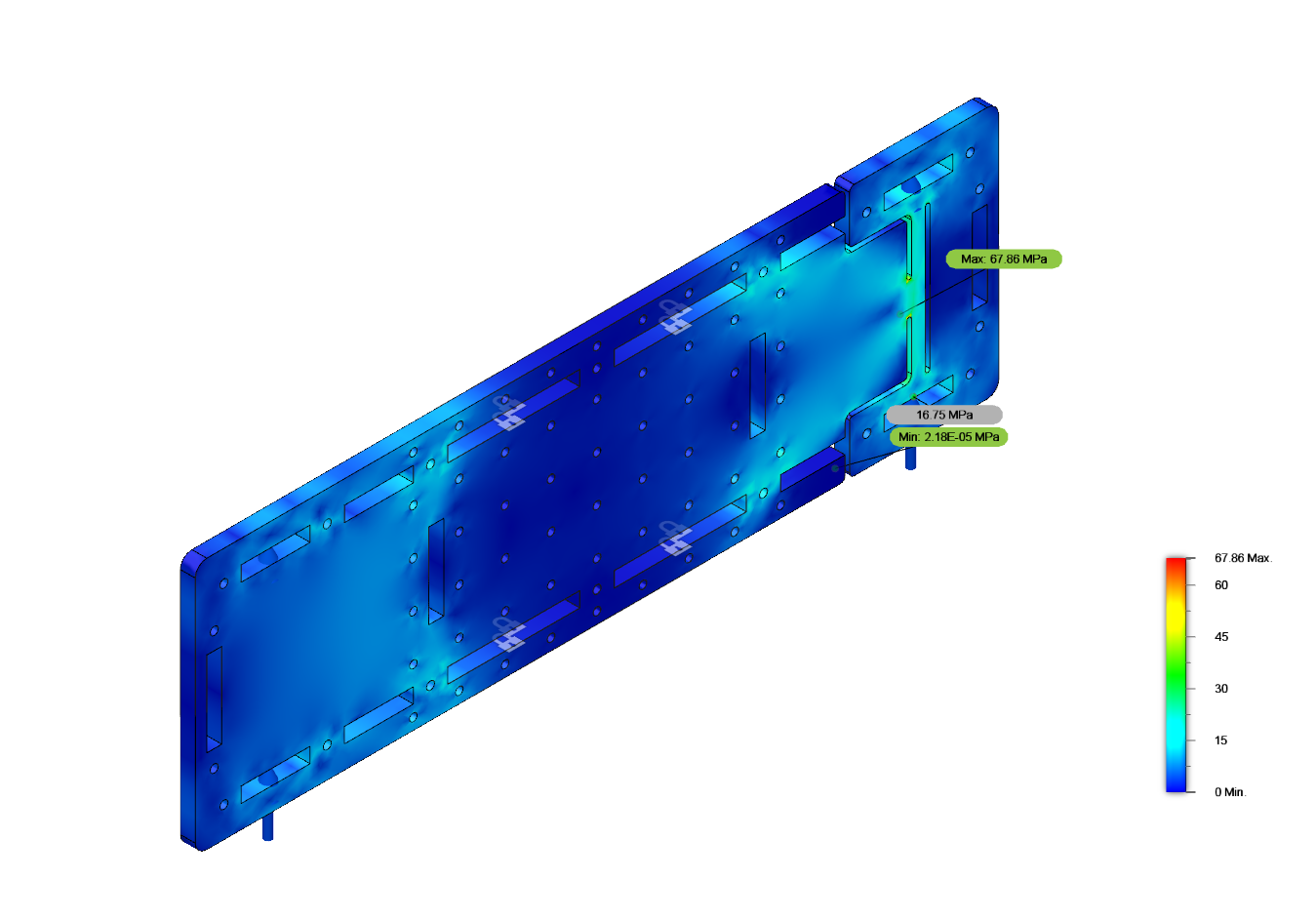
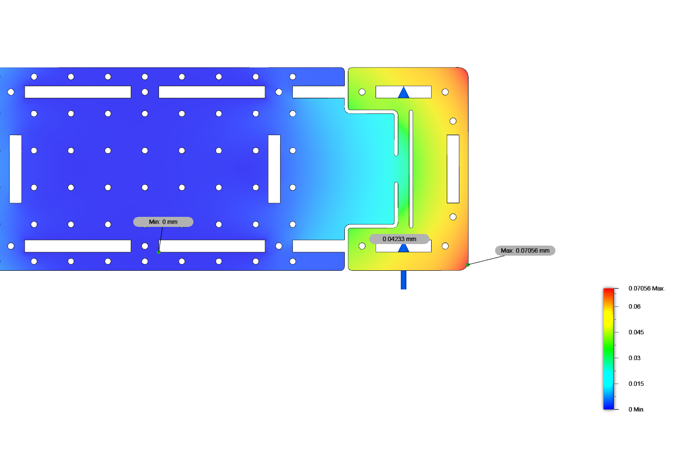
FEA
I ran a quick simulation to see that this flexure was OK. Here it is loaded in the direction it is meant to be stiff in, with 2.5kN applied vertically. There are two of these members being tested so this would be equivalent to 5kN of force, about where I expect this thing to top out. Displacing about 40uM (I'm looking at the face-to-face distance between the loaded zone and the fixed zone, not that rotation that appears from my non-rigorous fea constraints) with 70MPa stress maximum.
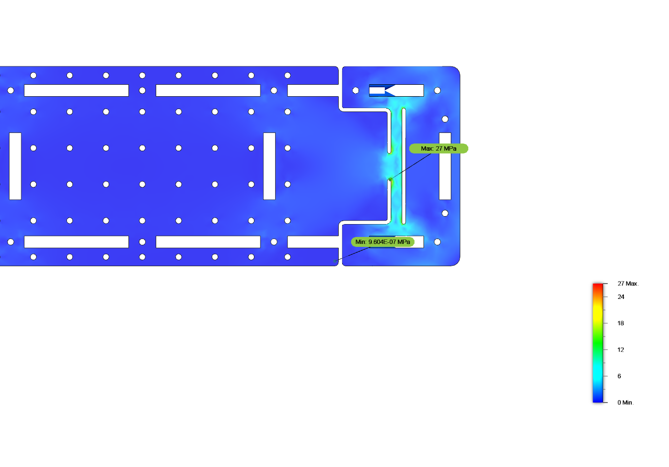
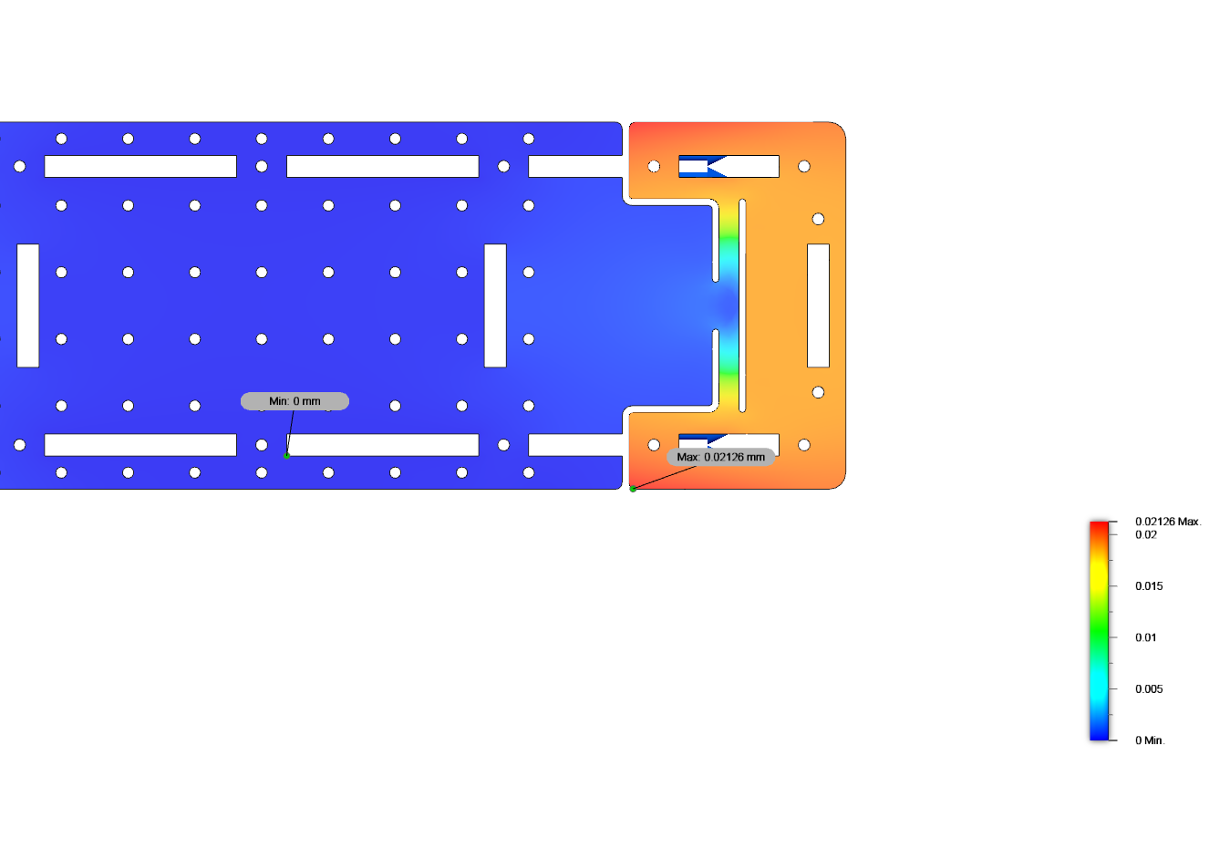
And out of plane, with 250N applied, about 20uM displacement. So 1/10th the load and 1/2 of the displacement, it's at least 5x stiffer in one DOF than the other. Is that grounds for a decent flexure?
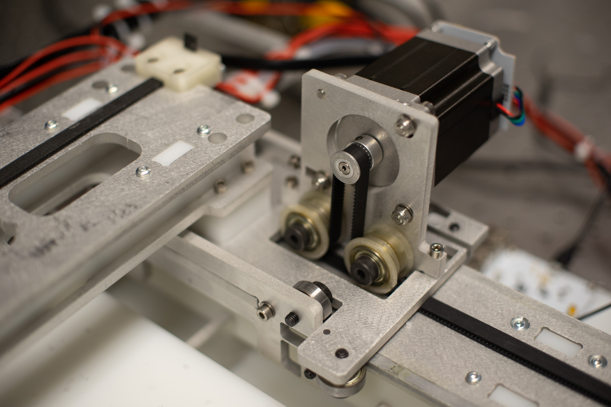
uSSM #1: Generalist does uSSM
To test requisite parts for a small stress and strain machine, I attached some jaws and a load cell to this 'generalist' machine.
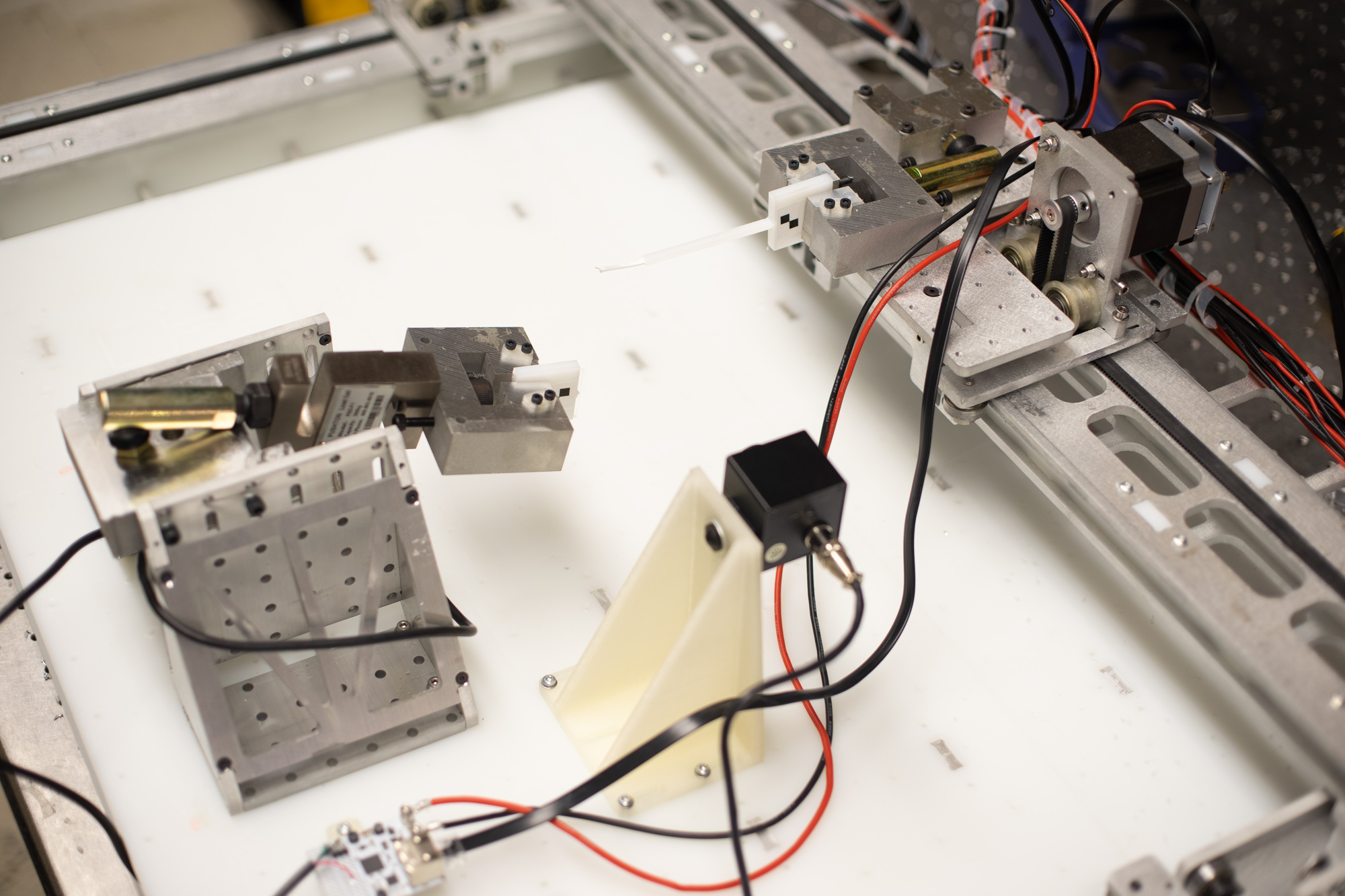
I used automatakit network controllers and atkapi to program the beginnings of a materials testing system: here I'm just stepping the axis along 25 steps at a time and capturing a photo on each step. No data yet.
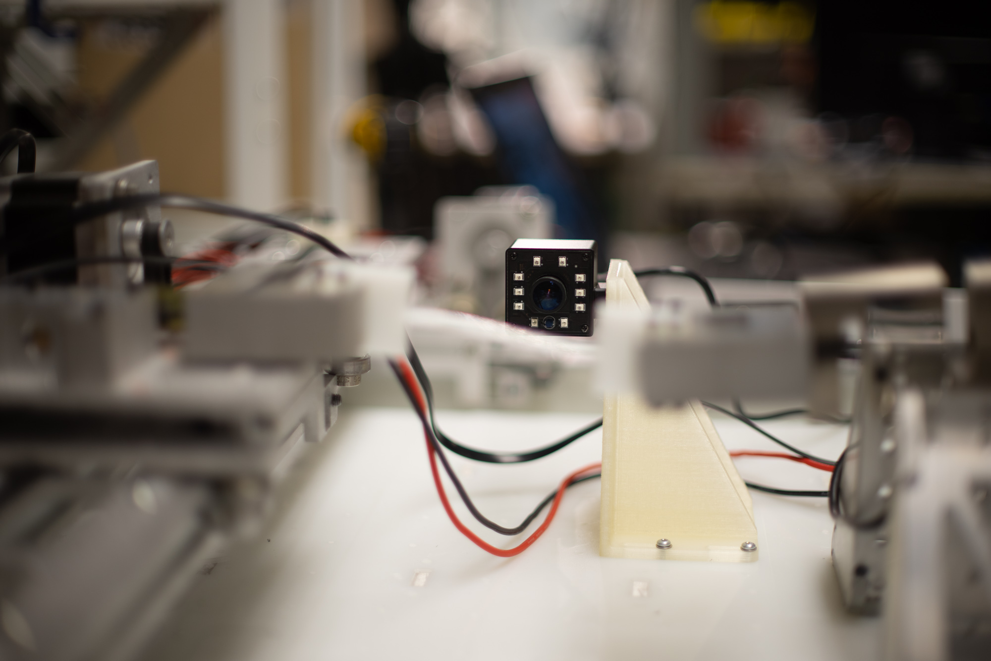

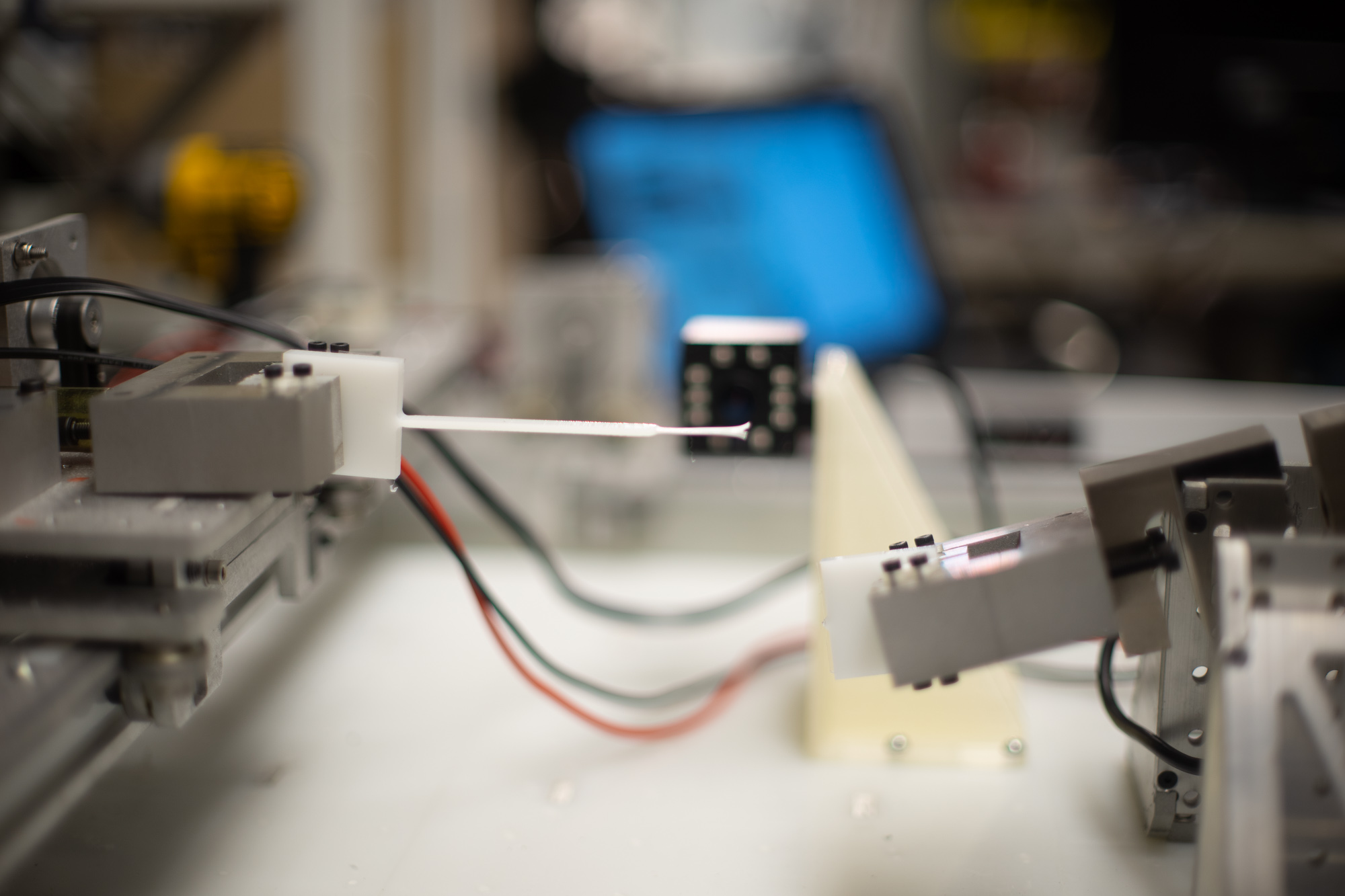
We're going to try to track the endpoints with CV, rather than fancy encoders etc. Sam has done some prior work on this, here.
Microphone Stiffness Testing
Alysia did this in FabAcademy and it would probably be a fun piece of kit / example for the NIST Project. Looks pretty simple... and compelling.